 Except where the bit wire touched the word cylinder the wire was straight.
The curved part touching the cylinder was in the middle of the bit wire.
This looked rather like a wide open safety pin with a (word) cylinder fit snugly thru the small hole.
Except where the bit wire touched the word cylinder the wire was straight.
The curved part touching the cylinder was in the middle of the bit wire.
This looked rather like a wide open safety pin with a (word) cylinder fit snugly thru the small hole.
This was about 1950. The pipe organs were sometimes about 50 years old which put their construction near 1900. There were several digital technologies employed in pipe organs. Dominant in large organs were either pneumatic or electric signals from the console (where the performer and keyboards were) to the chambers that held the pipes. This distance might be 50 feet or more. The control bundle would be either a bundle of lead tubes, each tube perhaps 2 mm inner diameter, or a bundle of wires carrying electrical signals. In either case there would normally be a signal per key and another per stop. There were, of course a few extras for extra controls and spares. Air flowing thru these signal tubes was not nearly sufficient to cause the pipe to sound; pneumatic logic in the chamber was necessary.
Another class of pipe organ is the tracker organ with mechanical linkage. The console of a tracker organ is very near the pipes. Consequently such organs are less modular and much harder to move. Also the keys are harder to depress for more mass is coupled to the key. Pneumatic or electric systems required only a very light touch. I have never worked on a tracker organ. Some modern tracker organs use very modern materials such as carbon fiber plastics to achieve low mass actions.
I don’t know when the first modular pneumatic consoles were built. I think it was late in the 19th century.
The information technologies of the early 20th century organs were significant. First it must be understood that a particular pipe is associated with a particular key and a particular stop. A particular key is a particular frequency, and a particular stop is some particular sort of sound varying from other sorts in overtones and other characteristics. The pipe plays only when the key is depressed and the stop is selected. Stop selection is under control of the performer and are seen typically on either side of the keyboards. It is more complicated than that. Some stops are an octave, or more higher than their mates, some lower. Sometimes two stops will call on the same ‘rank’ of pipes but with an octave, or more difference in pitch. Some ‘couplers’ associated with a particular keyboard will act as though pressing a key on that keyboard will effectively press another key on the same or different keyboard, perhaps at a different octave.
The digital logic was sometimes built with pneumatic relays where an electric signal would operate a valve that would release air to inflate a bellows to move from 5 to 30 electric contacts in a gang action. (Multi pole, single throw.) The bellows were perhaps 4 by 6 cm in size and would open by moving about 0.5 cm. The reaction time of these was good enough to not add too much latency to the signal. Electric signals (about 6 volts, I think) went to solenoids, one per pipe, that controlled a valve that controlled air flow to the pipe. The air pressure is from 6 to 11 ‘inches of water’. Note that the pipes were perhaps 50 feet from the organist and the resulting 50 ms latency was rather more than the pneumatic relays introduced.
Another significant feature, that may not have arrived until the early 20th century was approximately the ‘electro pneumatic capture system’ as described in this article. The system that I examined was a bit different from the above article. Several ‘pistons’ would live between the keyboards. They appeared as cylindrical buttons that could be pressed by the performer. The organist would rehearse one day and select appropriate stops. He would then choose some unused piston and press it while a special write mode console control switch was temporarily on. This operation captured the current selection of stops. On a subsequent performance he could press that same piston again and the set of originally selected stops would be automatically selected again. This was a binary word oriented memory in all but name. There might be 15 combination pistons each of which might control 60 stops. Some pistons controlled only the stops for its own keyboard.
The 1900 technology for this binary word memory was very clever.
First of all it was field writable and non-volatile.
In the version I studied there was a very stiff steel cylinder about 3 mm in diameter—the word cylinder.
The bits of one word were spaced along this cylinder perhaps 2 bits per cm.
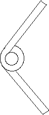
Each bit consisted of a 4 cm long stiff metal wire perhaps 1.5 mm in diameter, tightly wrapped around the word cylinder, about 1.2 full turns.
Except where the bit wire touched the word cylinder the wire was straight.
The curved part touching the cylinder was in the middle of the bit wire.
This looked rather like a wide open safety pin with a (word) cylinder fit snugly thru the small hole.
The magic of this configuration was that pressing on the end of the bit wire so as to turn the wire about the axis of the word cylinder, came in two forms:
Perpendicular to the word cylinders were the stop rods, two per stop, one on either side of the plane of word cylinders. The ends of the bit wires protruded thru slots in the stop rods. To write a word into memory one first moves the stop rods along their long axis to reflect the current stop settings. (They are probably already there.) Then the word cylinder to be written is twisted back and forth to adjust each bit to remember the position of the stop rods. This motion is always in the direction that the coiled bit wires permit. To read the word the stop rods are biased in the direction of resistance to relative turning, and then the word cylinder is twisted as upon write. The unyielding bit lines seize up and push the stop rods, each to their desired position. This position is sensed and the operator set stop controls, are set by pneumatic action. It is a form of hysteresis and servo mechanism.
(More detail—perhaps to be integrated) There were two motions to the stop rod pairs. For one stop the two rods, on either side of the plane of word cylinders, would move, each along their axis, but in opposite directions; the motion was perhaps 1 cm. This relative position of the two rods represented whether the stop was selected. The other motion was in common with all of the stop rods and was in common with all stop rods. This common motion was in the same direction for stop rods on either side of the plane of word cylinders. This motion was also about 1 cm. One of these two positions was for reading the memory, and the other position was for writing the memory.
The organ that I studied was already many years old and this mechanism needed no repairs. It was rusty but worked flawlessly. I think that this mechanism was in an Aeolian-Skinner instrument. I write this in the past tense, but I suspect that their organs may be in service today.